This blog comprehensively covers all the key steps involved in the reverse engineering process including 3D scanning and STL file modification. It also talks about how different software and their latest updates can help in speeding up and simplifying the whole process.
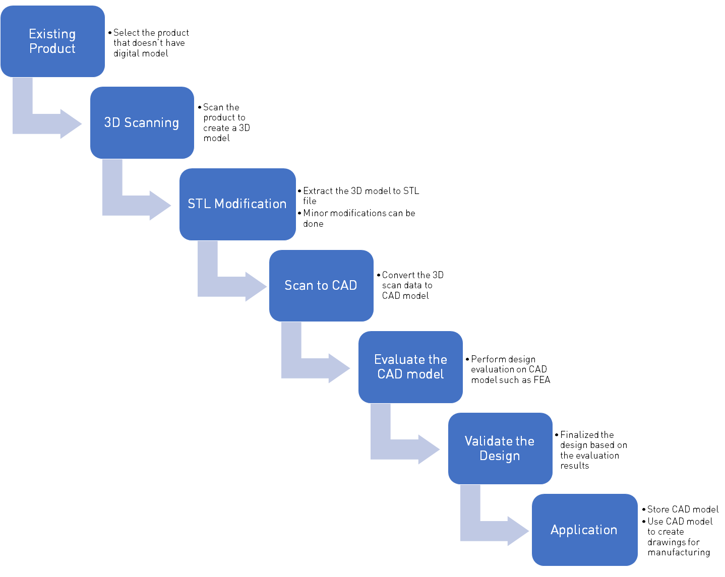
Reverse Engineering (RE) is a process of creating 3D design from existing part, component or assembly. The term is coined due to its backward direction approach for making components. Over the years with the development of CAD software, 3D scanners, and 3D printing technology reverse engineering has become an important tool for product designers and manufacturers.
3D SCANNING
DEFINITION
One of the methods to make a 3D model of a part is 3D Scanning. It is used to capture the shape, size, and texture of an object. The output of scanning is a 3D file that can be edited and saved. There are multiple methods to make a 3D model.
METHODOLOGY
1. Digitizing:
It is the contact-based method for collecting 3D data. The most common application of digitizing is Co-ordinate Measuring Machine also known as CMM. The probe slides against the surface and the cloud point data is captured. The probe can be point or ball type and it collects 3D data points in space. This method is more suitable for geometric shapes rather than freeform organic shapes.
2. LASER Scanning:
It collects 3D data points by passing a laser line over the surface of the object and then collecting it on a sensor. It is quick and very useful when scanning freeform organic shapes. It can capture every minute details which cannot be captured using digitizing. Also, large objects such as cars, artifacts, or sculptures are easy to scan with laser scanning. Sometimes the object being scanned cannot be touched such as clay models, antics, etc. In that case, laser scanning is more suitable.
3. Photogrammetry:
This technology is used for creating 3D model from photographs. There are multiple tools available that can be used to generate 3D model. The quality and accuracy of the 3D model depend on no. Of photos, quality of photos, tools used to create 3D model. No. Of photos ranges from 1 to 100s and the processing time is directly proportional to it. Some tools require pre-processing and post-processing for cleaning the 3D models.
The output of a 3D scan is generally a STL or OBJ file. Lets understand what are the different methods to work with this file.
STL FILE
STl file is a tessellated surface model. After scanning, it might be required to modify the model. But the STL file cannot be modified easily like a CAD file. It either requires a conversion to a solid model or a specialized tool that is designed to modify STL files. There are three ways to manipulate an STL file.
STL MODIFICATION METHODS
1. Feature based modeling using STL file
In this method, STL file is first imported into the CAD software as a solid body. Feature-based modeling is then used on the model and every feature being created to match the STL file gets added in the feature tree. An alternate approach could be to make a CAD file by measuring dimensions from STL and then creating a new body in CAD, but its less efficient to do it that way. Conversion to solid file will only work for shapes, which does not have very complicated surface. If this conversion doesn’t work, then you may have to convert it to surface body and work on it, which will make it slightly more complicated.
2. Sculpting
There are tools available that can be used to modify STL files. These tools are generally known as sculpting tools and used for creating 3D sculptures, environments, and animations. Since these tools are specially designed for sculpting, they have wide variety of options to modify an existing STL file, but that also requires good training for its effective use. They can be also used to modify meshed surfaces. There are multiple sculpting software in the market, out of which some are paid and some are open source. Below is the list of some of the software that are popular for sculpting.
| Sr. No. |
Software |
Features |
License |
| 1 |
Blender |
Sculpting, 3D modeling, Rendering, Animation |
Free |
| 2 |
Zbrush |
Sculpting, 3D modeling, Rendering, Animation |
Paid |
| 3 |
Meshmixer |
Sculpting, 3D modeling |
Free |
| 4 |
Autodesk Mudbox |
Sculpting, 3D modeling, Rendering, Animation |
Paid |
| 5 |
Autodesk 3DS Max |
Sculpting, 3D modeling, Rendering, Animation |
Paid |
| 6 |
Autodesk Maya |
Sculpting, 3D modeling, Rendering, Animation |
Paid |
Although, all of them offers similar features there are differences in capabilities and tools available.
3. Convergent Modeling
Convergent modeling converges meshes (called facet models) and solids (called classic b-reps) into a single model. It’s a new technology that is available in Siemens NX and Solid Edge. It lets you import a scanned 3D model as a convergent body and then feature based modeling can be used on the body. It eliminates conversion from one format to another and reduces the risk of loss of details. Although this method is only available in NX and Solid Edge, other software such as PTC Creo and SolidWorks will be offering similar technology in new updates.
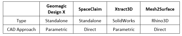
STL TO CAD DIRECT CONVERSION SOFTWARE
There are software available that can be used to convert scanned 3D models into a conventional history-based feature model. Below is a brief description of some of those software:
1. Geomagic Design X
Geomagic Design X is a complete reverse engineering software that converts scanned data into a history-based model with little or no human inputs. It can create planes, sketches, and features automatically from scanned data. The CAD feature history can be exported to CAD software such as SolidWorks, NX, Solid Edge, Inventor, Creo.
2. SpaceClaim
SpaceClaim is also standalone software. It uses direct modeling approach to create CAD models from STL files. It is very efficient in handling STL files. It can quickly create complex solid bodies from scratch. It can trace the facets of STL file and create curves from it. It also helps in cleaning messy and noisy scans. Worn out parts of scanned components can be modified.
3. Xtract3D (Plug-in for SolidWorks)
It is a specialized and affordable plug-in available for SolidWorks for reverse engineering. It works as an Add-in in SolidWorks native environment so the interface remains similar to SolidWorks. Keeping 3D scan data as reference, CAD model can be created by manually extracting features and sketches with the help of available tools. This is a fool-proof way of converting a scan model to CAD model. Xtract3D can handle large scan data files very well without lagging issues.
4. Mesh2Surface (Plug-in for Rhino3D)
Mesh2Surface is a plug-in that can be incorporated in Rhino3D to create CAD models from 3D scanned data. It offers similar tools for creating 2D sketches. Main features of the Mesh2Surface is 3D sketches that can be used to draw on mesh and Autosurface tool to extract freeform organic surface.
ADVANTAGES
- It helps in exploring existing products and designs, which can be further used in creating or improving a new design.
- Outdated or obsolete designs can be reconstructed with the help of reverse engineering.
- Reverse engineering can be used to evaluate the designs that are decades old to find strength and flaws of the design. This can lead to better designs in future with improved quality products.
- Reverse engineering can be used to shorten design lead cycles, to quickly release the product in the market. The cost of the product also reduces with shorter lead cycles.
- Reverse engineering helps in creating a CAD model for future reference. The CAD model can be stored and used when required.
LIMITATIONS
- Gaining a deep understanding of the design is impossible.
- Irreversible processes that the product has gone through such as hardening, tempering or other heat treatment or similar processes cannot be predicted or replicated accurately.
- Initial cost of set up is high, but there is always an option of outsourcing.
- Ensuring the legal feasibility of the product being reverse engineered can be lengthy and expensive.
IMPROVIANS TAKE
Reverse engineering has come a long way in recent years due to improvements in software, scanning technologies and increased demand generated due to 3D Printing. Scanning and obtaining the 3D model is relatively easy. The longest lead-time is in modifying the model or converting it into the feature based CAD. For creating CAD from scanned data, Geomagic Design X is the best software available. It has all the tools required to complete any reverse engineering task. The only drawback of Geomagic Design X is the cost, but if your reverse engineering requirements are frequent then it is worth to get a full-fledged package. SpaceClaim is a good alternative for Geomagic Design X and cost can also be deemed as affordable. Xtract3D and Mesh2Surface are also affordable alternatives if you already have the CAD packages SolidWorks or Rhino3D. Geomagic also offers a plug-in for SolidWorks for reverse engineering known as Geomagic for SolidWorks. The major advantage of Geomagic and Xtract3D is parametric modeling which most of the designers are familiar with. SpaceClaim and Mesh2Surface uses direct modeling approach to create CAD model which is quicker but bit difficult to adapt. So, for reverse engineering project all of this has to be taken into consideration. At Improvians, we can help you with end to end reverse engineering requirements.